
{des3:0} This chapter describes all drawing primitives that can be used on a graphical schematics sheet as well as the data structure of the graphical schematics sheet.
{des3:1} A drawing object is a drawing primitive, a group or a sheet.
{des3:2} A drawing object is fully specified by:
{des3:3} Properties are fields that are typically not stored or edited by the user in plain text form, and/or are produced and consumed by the code and are not interesting for the user. Attributes are typically textual data that are easy to edit as text.
{des3:4} All properties are present in the memory and file format. When a property needs to be "turned off" (e.g. a group should not be rotated), the property still has its slot in the file format and in the memory, but the value is set to a special "unspecified" value.
{des3:5} A valid cschem implementation must implement the functionality of all mandatory properties. If an implementation does not implement the functionality of an optional property, the implementation must be able to load, store and save the value of that property. Whether the functionality of a property must be implemented or not can be found in the mandatory column of the property tables.
{des3:6} All attributes are optional.
{des3:7} Drawing objects are stored in a tree structure, with the top level single root being the sheet and leaves being atoms.
{des3:8} The following figure demonstrates the tree structure (parent -> child). Rectangular objects have attributes.
| {des3:9} drawing object types | |||||
|---|---|---|---|---|---|
| term | type | properties | attributes | children | summary |
| line | atom | yes | no | none | straight line segment |
| arc | atom | yes | no | none | circular arc |
| spline | atom | yes | no | none | (spline) |
| text | atom | yes | no | none | multiline text |
| polygon | atom | yes | no | none | polygon with curved edges |
| connection | atom | yes | no | none | logical connection |
| bitmap | atom | yes | no | none | embedded bitmap |
| group | composite | yes | yes | atoms, composites | group of atoms and composites |
| group_ref | composite | yes | yes | atoms, composites | reference to another group |
| sheet | sheet | yes | yes | atoms, composites | root of the tree |
{des3:10} An oid is a signed 32 bit integer. Any time a new drawing object is placed on a sheet or within a group, the new drawing object's oid is set to the group's or sheet's next_oid and the group's or sheet's next_oid is incremented.
{des3:11} The oid value 0 means "invalid" or "unused" or "unspecified". Any non-zero oid is a valid drawing object ID. The same oid can not be attached to two different drawing objects within a group or sheet.
{des3:71} Only positive oid values shall be used in files or communication, negative values are reserved for application-internal use.
{des3:12} The oid is used for referencing drawing primitives within the group or sheet. It is meant for internal references only: external objects, such as other sheets, shall not use oid to reference into the sheet.
{des3:13} If next_oid overflows, oids are allocated using a slower mechanism that still result in unique numbers. If there are 2^32-1 drawing objects on the sheet, no more drawing objects shall be added.
{des3:72} An oid-path is a slash separated list of oids. It is a top-down description of an object path: it contains zero or more composite object oids then descending through groups until reaching the final object that's being addressed.
{des3:73} An oid-path is always an absolute path, root being the sheet. An oid-path is invalid if any prefix path of it refers to a non-existing object. The leading slash is mandatory.
{des3:14} color: 24 bit #rrggbb (2 digit numbers written as hex, 00 means darkest, ff means brightest). There is no alpha, there is no drawing object level translucency.
{des3:15} Most drawing objects are drawn with a pen.
| {des3:16} pen properties | ||
|---|---|---|
| property | mandatory | description |
| name | yes | string: name assigned by the user; used for addressing pens; unique within the group |
| tip shape | yes | circle (also called round) or square; when square, an edge of the square is always aligned with the stroke direction |
| tip size | yes | circle diameter or square edge length in coordinates |
| color | yes | |
| font_height | yes | font height in coords for text objects (string) |
| font_family | no | hint: font family name for text objects (string) |
| font_style | no | hint: font style for text objects (string; e.g. bold, italic) |
| dash | no | dash pattern |
| dash_period | no | length in coords a full dash pattern cycle |
{des3:17} When using a pen, the base geomerty is specified as the single, 0 wide centerline. For a round tip pen, this means the actual rendered pixels extend to exactly ((tip size)/2) pixels in all directions from any point of the base geometry. For example if the base geometry is a 10 units long horizontal line and the tip size is 4, the total length of the rendered line is 2+10+2=14 units.
{des3:18} Dash pattern: an unsigned 16 bit integer, a bit pattern, each bit represents 1/16 dash_period long stroke, 1 means draw, 0 means invisible. If dash value is 0x0000 or 0xFFFF or dash is not specified, solid stroke is drawn. If dash_period is not specified or 0, it is (tip size)*128.
{des3:74} Pens are defined per group. When an object refers to a pen, it uses the name of the pen. The pen is searched first in the group of the object; if not found, in the parent group, then in the grandparent group, etc. If no pen with the given oid (or name) is found when reaching the root, a warning is issued and a safe (implementation-specific) default pen is used.
{des3:19} Coordinates on the sheet are stored as unit-less integer x;y. Negative coordinates are supported. The drawing has no special spot, the user is free to use any coordinate values. The point at 0;0 is not special either, but it is recommended that the first drawing object of a new design is placed near to 0;0 to allow the design to expand in any direction.
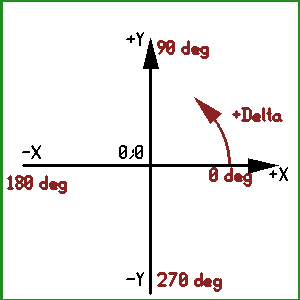
{des3:20} Cschem implementations are expected to handle at least 32 bit wide, signed integer coordinates. When a drawing is presented in normal orientation, the X axis is horizontal, increasing to the right, the Y axis is vertical, increasing upward.
{des3:21} Angles are specified in degrees between [0 .. 360) for absolute values and between [-360 .. +360] for relative values. Degree 0 is at x>0;y=0; positive angle is toward CCW. Angles are stored as floating point numbers, with precision at least matching the binary32 (single precision) of IEEE 754.
{des3:22} The coordinate system is demonstrated by the following figure:
{des3:80} Every drawing and group object has these properties with the same meanining. These common properties are not listed in each object type's property list in the following sections.
| {des3:81} common properties | ||
|---|---|---|
| property | value | description |
| lock | boolean | if true, the object is locked (should not be selected or edited individually); if not specified, defaults to false |
| floater | boolean | if true, bypass the "group lock"; non-floater objects are group-locked by default (can't be selected or edited individually) if they are part of a group other than sheet's direct; if not specified, defaults to false |
{des3:23} A straight line segment represented by a single contour line and no fill and no attributes and no children.
| {des3:24} line properties | ||
|---|---|---|
| property | mandatory | description |
| oid | yes | |
| p1 | yes | x;y coords of the starting point |
| p2 | yes | x;y coords of the ending point |
| stroke | yes | pen to use for drawing the line |
{des3:25} Stroke may be unspecified if the line is part of a polygon outline.
{des3:26} An arc segment represented by a single contour line and no fill and no attributes and no children.
| {des3:27} arc properties | ||
|---|---|---|
| property | mandatory | description |
| oid | yes | |
| cx, cy | yes | x;y coords of the center point |
| r | yes | radius in coord units |
| sang | yes | start angle [0..360) |
| dang | yes | delta angle [+-360] |
| svalid | no | boolean to indicate whether start-point coord is valid |
| sx, sy | no | exact x;y coords of the start-point |
| evalid | no | boolean to indicate whether end-point coord is valid |
| ex, ey | no | exact x;y coords of the end-point |
| stroke | yes | pen to use for drawing the line |
{des3:28} The exact endpoint x;y; coords are specified as an optional helper. In case the endpoint may matter for visually connecting drawing objects, the implementation may emit and load the endpoints. Either none of the endpoints are specified or both endpoints are specified.
{des3:29} Optional: an implementation loading the drawing object may use the endpoint to detect or even correct rounding errors either in the loader implementation or in the emitter implementation. If the calculated endpoint differs from the stored endpoint by more than 1/4 of the tip size, the implementation shall recalculate other parameters of the arc to match the endpoints.
{des3:30} If an implementation doesn't implement support for the endpoints, it must invalidate the endpoint values upon any coordinate change to the arc, but must preserve the endpoint properties upon other changes or no change.
{des3:31} Stroke may be unspecified if the arc is part of a polygon outline.
{des3:32} Not supported in the first version.
{des3:33} The text object has properties and no attributes and no children.
{des3:34} It represents a multiline text block arranged in a bounding box. When x2 and y2 are specified, pen font height is taken only as a hint: the renderer may chose a different font and size but has to find the closest possible match for fitting the unrotated text in the bounding box. When x2;y2 are not specified, the lower left corner of the rendered text is placed on x1,y1 and text size is chosen for the pen font_height property. Rotation is performed after the above bounding box or pen font height rendering.
| {des3:35} text properties | ||
|---|---|---|
| property | mandatory | description |
| oid | yes | |
| x1, y1 | yes | x;y coords of bounding box bottom-left (smaller coords) |
| x2, y2 | no | x;y coords of unrotated bounding box top-right (larger coords) |
| rot | no | rotation |
| mirx | no | boolean; mirror X coords (mirror over y axis); default is false if not specified; affects origin vs. bbox relation, does not affect pixels fo rendered text |
| miry | no | boolean; mirror Y coords (mirror over x axis); default is false if not specified; affects origin vs. bbox relation, does not affect pixels fo rendered text |
| halign | no | horizontal alignment, per text line: start, center, end, word-justified, justified (default: start); affects only bbox specified text and multi-line text; start means toward the text object's origin |
| text | yes | string |
| stroke | yes | pen used to determine color and font properties |
| dyntext | yes | boolean; when true, perform dyntext substitution |
{des3:79} Rotation is specified in degrees, taken as 0 if the field is not specified. Zero means horizontal text, positive degree is CCW rotation around x1, y1.
{des3:36} Horizontal alignment is considered only in two cases. First, in singleline bbox-specified text that is narrower (horizontally) than the box; second, in multiline text where the width of the bounding box matches the width of the widest text line. This property determines how to handle the narrower lines. Word-justified means spacing should be applied in between words only; justified means the implementation is free to use spacing between characters too.
{des3:37} The text field is plain 7 bit ASCII. The implementation may optionally interpret "&hex;" and/or "&name;" Unicode sequences - users shall not expect this to universally work across implementations; portable schematics shall not use them. Line boundaries indicated by single \n characters.
{des3:75} If dyntext is true, any %pattern% is substituted in text before rendering. The syntax of pattern is:
{des3:76} Multiple ../ can be used to traverse the object tree up; the root node's parent is itself. Addressing can be done only upward, it is not possible to address sibling nodes. Non-existing properties or attributes are substituted with empty string.
{des3:77} A typical example is the "refdes text" which is a text object within a group role=symbol, with dyntext true, text field containing: %../a.name%.
{des3:82} In case the addressed attribute is an array: if it has only one element, it is substituted; else <array> is printed.
{des3:38} A polygon is represented by a complex outline, an optional fill, and no attributes and no children.
| {des3:39} polygon properties | ||
|---|---|---|
| property | mandatory | description |
| oid | yes | |
| outline | yes | list of atoms, see below; these atoms are the children of the polygon in the data tree |
| stroke | no | pen or unspecified if no stroke is required |
| fill | no | pen or unspecified if no fill is required |
{des3:40} The outline is an ordered list of lines, arcs and splines that specify the contour. The list is specified in CCW on both drawing object level and endpoint level. If there's a gap between the endpoints of two consecutive drawing objects, a straight line is assumed for the missing segment.
{des3:41} To avoid degenerate cases, the contour list has further restrictions:
{des3:42} Individual stroke of each outline object is ignored and the outline is interpreted as a theoretical, 0 width contour. This theoretical contour is drawn with the polygon object's stroke (when specified).
{des3:43} If the fill property is specified, the polygon is first filled with the color of the fill pen. If the stroke property of the polygon is specified, this pen is used to draw the outline contour of the polygon (rendered after the fill).
{des3:69} A rectangular, scaled bitmap image.
| {des3:70} line properties | ||
|---|---|---|
| property | mandatory | description |
| oid | yes | |
| p1 | yes | x;y coords of the top left corner of the bounding box |
| p2 | yes | x;y coords of the bottom right corner of the bounding box |
| transp | yes | if set, the value of the pixel that should be considered transparent; the value is in the same pixel format as the pnm |
| pnm | yes | a Portable Anymap in P1, P2, P3, P4, P5 or P6 format |
{des3:44} The graphical sheet does not imply connections based on geometrical features, e.g. when the endpoint of a "wire" happens to be on the endpoint of a "pin". Instead, all connections are created and stored explicitly by connection objects.
{des3:45} The connection object is invisible and refers to other objects. It has properties but no attributes and no children.
| {des3:46} connection properties | ||
|---|---|---|
| property | mandatory | description |
| oid | yes | |
| conn | yes | list of connected drawing objects (see below) |
| gfx | yes | oid-path if the drawing object that's the graphics of the connection, or invalid oid |
{des3:47} The connection always connects groups, because only groups can represent abstract objects. The conn field is a list of oid-paths of drawing objects (typically atoms) that are directly contributing to the connection. The groups connected are the direct parent of the objects listed. Such parent group is always a group or a group_ref with one of the following roles:
{des3:48} The conn list must list drawing objects so that at least two different (parent) groups are referred.
{des3:49} If the gfx oid-path is not invalid, it refers to a drawing object (e.g. an atom or a group) that graphically represents the connection.
{des3:50} The most common use case is marking the graphically overlapping parts of two or more groups a logical connection. The GUI detects the new connection from user draw actions and creates (or extends an existing) connection object. The typical gfx of a connection is a small dot drawn as a zero length (round cap) line with pen size at least twice of the usual wire style's.
{des3:51} Since the connection is a logical concept, it can be realized between two groups that do not have graphically overlapping parts. However, using connections that way is not intuitive for the user of a graphical editor, and cschem implementations generally should refrain from doing that. Overlapping objects (e.g. crossing wirenets) don't necessarily connect (no connection object is made for disconnected crossings).
{des3:52} Conceptually a connection is similar to a junction within a wirenet group but it is between two groups (but shall not connect two wirenets - connected wirenet groups shall be simply merged).
{des3:53} Group objects consist of properties, attributes and a list of members (children).
| {des3:54} group properties | ||
|---|---|---|
| property | mandatory | description |
| oid | yes | |
| next_oid | yes | signed 32 bit integer (see above at common drawing object properties) |
| memb | yes | list of 1 or more member objects; these drawing objects are the children of the group node |
| rot | yes | rotation angle around x;y; can be 0 for no rotation |
| x, y | yes | x;y offset; can be 0;0 for no action |
| mirx | no | boolean; mirror X coords (mirror over y axis); default is false if not specified |
| miry | no | boolean; mirror Y coords (mirror over x axis); default is false if not specified |
| purpose | no | arbitrary textual name generated for local lib root groups, first level of groups in the sheet's indirect group |
| uuid | no | universally unique ID for referencing the group from external sources |
| src_uuid | no | if the group was copied from an existing group, universally unique ID of the source group it was copied from |
| {des3:55} group attributes | ||
|---|---|---|
| attribute | value | description |
| role | one of 3.3.3. | specify what concrete object the group represents |
{des3:56} The list of members consist of 1 or more atoms or composites. If the rotation angle is specified, first the coordinates of members are rotated around the rotation center. If any of the mir* fields are true, mirroring is performed then. If the offset is specified, the coordinates of members are shifted by the offset before the rendering.
| {des3:58} group_ref properties | ||
|---|---|---|
| property | mandatory | description |
| oid | yes | |
| ref | yes | reference to an existing group |
| rot | yes | rotation angle around x;y; can be 0 for no rotation |
| x, y | yes | x;y offset; can be 0;0 for no action |
| mirx | no | boolean; mirror X coords (mirror over y axis); default is false if not specified |
| miry | no | boolean; mirror Y coords (mirror over x axis); default is false if not specified |
| child_xform | no | see below |
{des3:59} The same attributes are available as for the group object. The group_ref and referenced group attributes are merged only while compiling the abstract model.
{des3:60} The ref field contains a reference oid-path.
{des3:83} The child_xform field is an unordered list of child transformations. Each element of the list contains a oid-path of a child object (relative to the referenced group) and one or more transformation command.
{des3:84} Each oid-path can be present only once on the list and each transformation can be present only once in a given entry.
| {des3:85} child_xform transformation commands | ||
|---|---|---|
| name | value type | description |
| movex | coord | child is moved (translated) in the X direction |
| movey | coord | child is moved (translated) in the Y direction |
| rot | angle (deg) | child is rotated |
| mirx | boolean | if true, child is mirrored left/right |
| miry | boolean | if true, child is mirrored up/down |
{des3:86} Order of transformations on each child object:
{des3:61} A group or group_ref is a drawing object, that can be the source of a concrete object. Each concrete object has only one source and each group (or group_ref) can instantiate only one concrete object. (Any multi-source merging, e.g. multiple symbols donating one element is done in the concrete -> abstract step.)
{des3:62} If a group (or group_ref) does not define a concrete object, it is a purely graphical feature that does not affect the concrete model, the abstract model or any output derived from these models - but still can affect graphical output.
{des3:63} Whether a group (or group_ref) is a source of a concrete object, and if so, the actual type of the concrete object is determined by the value of the "role" attribute of the group (or group_ref). The value must be one of those listed in the table below.
| {des3:64} role attribute values | |
|---|---|
| name | documentation |
| bus-net | des2:45 |
| bus-terminal | des2:25 |
| hub-point | des2:57 |
| symbol | des2:18 |
| terminal | des2:24 |
| wire-net | des2:13 |
| junction | des2:81 |
{des3:78} An empty or missing role attribute means the group is a logical grouping and does not directly create a concrete object. Such logical grouping can be used by the user or the GUI to group objects together. For example the user may draw arrows using lines and polygons to represent some logical relation between areas of a sheet; to be able to easier move/copy/delete an arrow, the user may use a custom group hosting the arrow.
{des3:65} Note: a junction connecting different groups can be created only by a connection object.
{des3:66} A (graphical schematics) sheet has two child root groups. The direct group lists all objects directly visible on the sheet, while the indirect group serves as a "local library", hosting invisible group objects that can be referenced from group_ref's from direct or used by plugins (e.g. devmap).
{des3:87} The first level under the indirect group is of "library" groups. Each "library" group has a "purpose" attribute that indentifies what kind of contents are collected there: which type of library the group hosts, which plugin(s) can edit it. For example the local symbol library is stored in the purpose=symbol group and devmap uses the purpose=devmap group to store locally saved devmaps. Library groups have no role attribute.
{des3:88} Furthermore a sheet has properties and attributes. The oid of the direct group is 2 and the oid of the indirect group is 1.
| {des3:67} sheet properties | ||
|---|---|---|
| property | mandatory | description |
| objects | yes | list of groups and atoms hosted on the sheet; these drawing objects are the children of the sheet |
| next_oid | yes | signed 32 bit integer (see above at common drawing object properties) |
| oid | yes | the sheet's own oid (to be used in parent references) |
| indirect | yes | "local lib" group for invisible objects, oid=1 |
| direct | yes | group for visible objects, oid=2 |
{des3:68} sheet uuid is the uuid of the direct group.