
Click the image to get the sch-rnd sheet
In this simulation we are going to map a simple opamp circuit's gain at different voltages (dc sweep).
The single-sheet schematic contains the opamp, the voltage sources for input and two more voltage sources for the power supply (positive and negative) for the opamp and spice command symbol.
This example uses the lm358 macromodel from sch-rnd's stock spice library. This model is a subcircuit of the amplifier and simulates a lot of limiters and parasitics.
The model uses the standard opamp pinout so the hardwired spice/pinnum attributes on the terminals will simply work.
V1 is generating the input dc voltage. We can leave it 0 here, since the dc sweep command for the analysis will provide the change over time
Both are 5V DC rails for powering the opamp with the required positive and negative supplies.
It contains the following script:
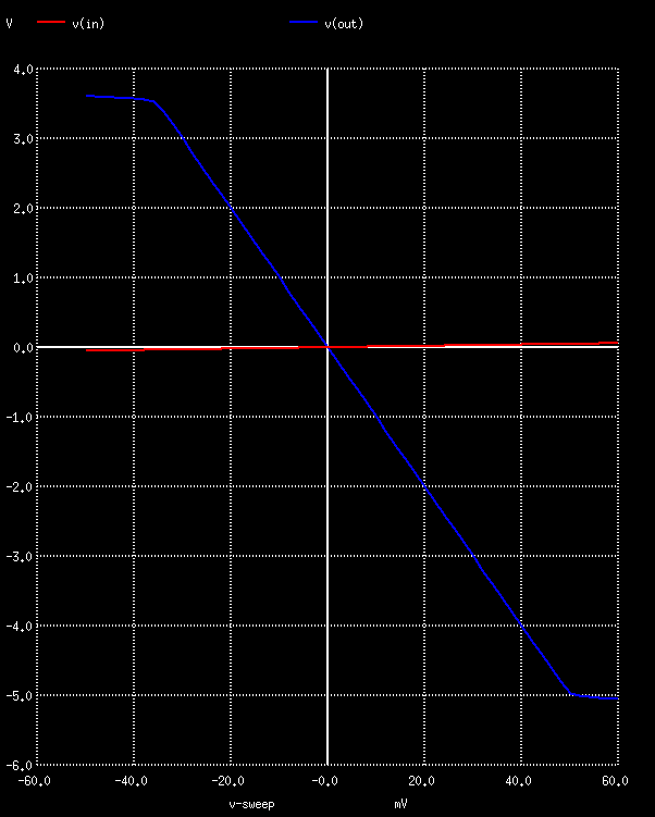
dc V1 -50m 60m 2m
plot v(in) v(out)
which runs a DC sweep analysis from -50mV to +60mV on the input, increasing voltage by 2 mV steps. At the end the input and output voltages are plotted.
Running ngspice the usual way on the export yields the following graph:
Gnucap throws an error: open circuit: internal node 14
Gnucap uses a different command syntax. Modify the spice command symbol's spice/command attribute to:
print dc v(in) v(out)
dc V1 -50m 60m 2m > plot.txt
After the export, write the single word spice in the first line of the file (e.g. using a text editor), otherwise gnucap won't know the file is in spice syntax. Then run gnucap 16_omapm_dc.cir and it will dump a text table to plot.txt that can be plotted using a suitable utility, e.g. gnuplot.
The gnucap-modified schematic is also available.
TODO