
Click the image to get the sch-rnd sheet
Mixed mode (analog + digital) simulation in the time domain.
The input and the output of the circuit are analog, but there is a section of digital circuitry inbetween (a XOR gate). The simulator runs the analog sections in the normal fixed time stepping manner while the digital section is simulated based on events. This makes large digital circuits simulate much faster at the expense of tracking digital lines only using low/high/unknown states, rather than simulating transitions in detail (rising/falling edges).
There are DAC and ADC converters inserted on the boundary of the analog and digital systems, using terminal attributes.
More info on the circuit: www.electronics-tutorials.ws
The XOR gate is going to use ngspice's internal model called d_xor. The whole model card is specified within the symbol, using the spice/model_card symbol attribute. The spice instance name must start with an 'A' for d_xor, while for other workflows the name U1 is more practical. This is dealt with by using the spice/prefix=A attribute.
ADC converters are installed on the input terminals of the XOR gate by setting the terminal attribute spice/bridge/model to bridge_adc_ttl, which is a sch-rnd stock spice model for TTL levels. Whenever spice/bridge/model is set on a terminal, target_spice will cut the original network connection of the terminal to insert a bridge component there. This component is not visible on the schematics, as it's specified in an attribute, but shows up in the abstract model for any view using target_spice.
In the case of ngspice, only one bridge component is placed per model, because ngspice's bridge components can handle multiple inputs and outputs in a 1:1 mapping.
(The sch-rnd user manual has more details on bridging)
The same bridging is done on the output terminal with model bridge_dac_ttl.
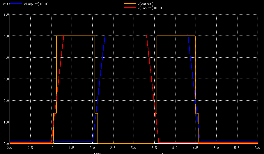
On the input, two pulses V1 and V2 are installed to generate trapezoid signals with slow rising and falling edges. This is to demonstrate how ADC goes from low to undefined to high. On the output a resistor is used to provide a DC path from the terminal to the ground - spice usually requires a DC path to the ground.
This example executes a normal transient simulation. Since most signals are either low or high most of the time, they would overlap on the plot. To avoid confusion, slight y offsets are introduced using an arithmetic expression, +0.0n.
tran 10ms 6s
plot v(input1)+0.04 v(input2)+0.08 v(output) xlimit 0 6s
Running ngspice the usual way on the export yields the following graphs:
Mixed mode simulation is not supported with gnucap.
TODO