Click the image to get the sch-rnd sheet; also requires this project.lht in the same directory
A notch filter built with two opamps: this filter passes signals between DC and 100 kHz but filters out 1 kHz signals. Demonstrated using a slotted opamp with simulation.
More info on the circuit: www.electronics-tutorials.ws
The lm358 contains two opamps in a single physical package. For the PCB workflow this is going to be a single footprint with 8 pins. For spice simulation, two separate components are exported, one per slot. The problem is: only slot 1's power terminals are connected! This is no problem for the PCB workflow, where a physical connection between slots exists within the package. For simulation, the trick is to set spice/shared on the power terminals on both slots (4 terminals total). This tells sch-rnd to share the connection between the same numbered terminals of different slots of the same symbol.
Other than this, everything else about the drawing is pretty much the same as in 12_bjt_amp_ac.
This circuit needs three voltage sources, which are both added as modifications. The first one is a DC 5V source connected to net Vcc (and GND). The second is a DC -5V source connected to net Vneg (and GND). These are the power supply rails of the opamp.
The third source is connected to the net in (and GND) and acts as the small signal AC source for the AC analysis, this it has a an AC value (of 0.1 V)
(Same as in example 06_passive_ac )
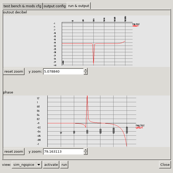
This simulation has two output configs, one for displaying the transfer (in decibel) and one for the phase (in radian). The reason for specify them in two separate output is the largely different y scale and unit.
The first output uses ac (dec) for analysis. This will feed in 10 different frequencies per decade and caputre the output. This also means the X axis, frequency, is logarithmic (common for frequency domain analysis).
The property to plot is vdb(out), which is the "voltage decibel" of the network called out. Instead of the net name a component-port could be specified within vdb().
The second output uses anlaysis previous, which means no new simulation is ran, but the data of the previous simulation is used. The presentation is also a plot of "out", but using the cph() function, which is the phase in radian.